“From out of the clear blue of the western sky comes Sky King.” When I was a kid “Sky King” ruled Saturday morning television. For those of you too young to remember, Sky King was a radio show first, and then a TV show, about an Arizona rancher who owned a cool plane (the Songbird), had exciting adventures, and caught bad guys.
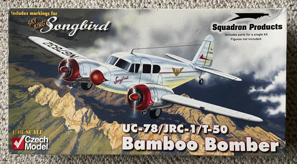
Last year, I could not resist buying a piece of nostalgia – I bought a Sky King model airplane. I also bought an airband radio, which picks up local aircraft to tower communications. Both are kits and I figured that they would keep me busy. I thought that it would be kind of fun to hang the model from the garage rafters, while listening to pilot-to-tower chatter.
Well, the model is still in the box, but I have taken on the radio. This is a $16.00 kit manufactured in China, so not a big investment. You have to put it together and figure out a few issues with the schematics as well. There are a number of these kits available for purchase on eBay.
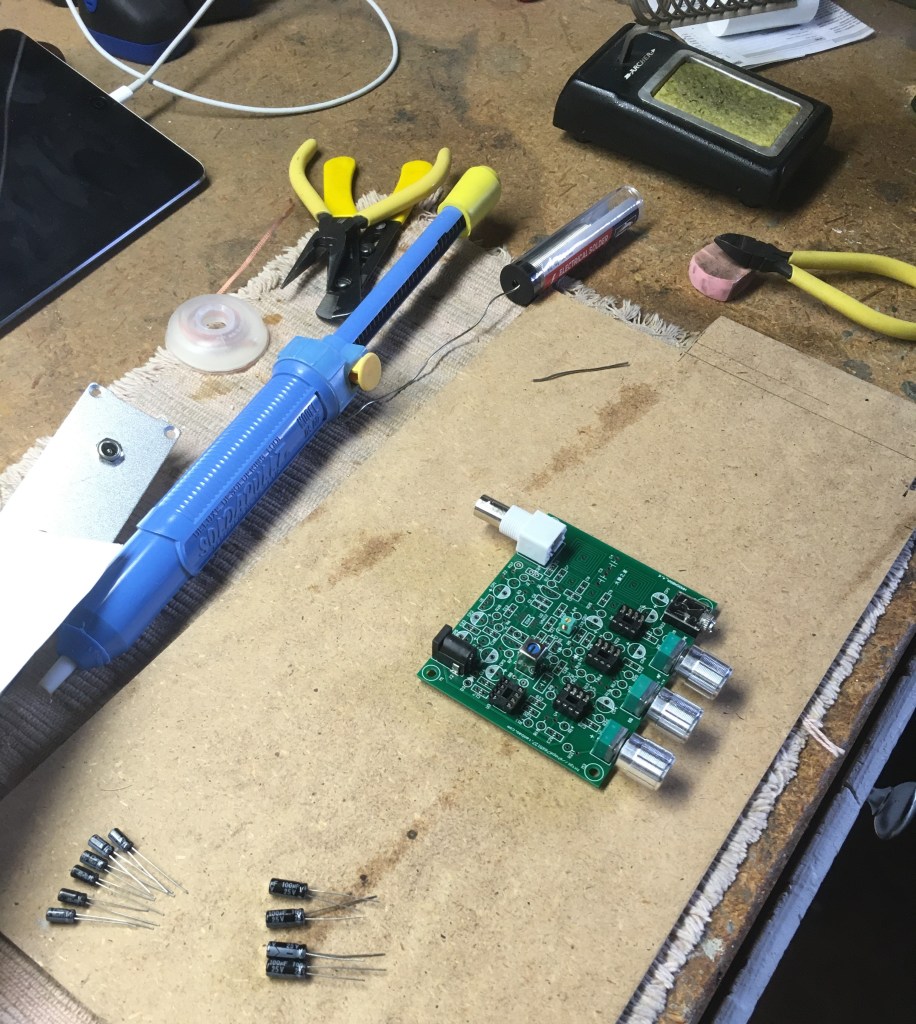
I laid out my tools and the electrical components, and the build began.

Mostly, you just follow the layout diagram, solder, and hope that you have received all the parts. I was missing one from the kit, but was able to substitute from my own inventory.
I also had to consult the web for help. I found a radio tech who had done a video on the same build. There were a couple of tips in the viewer’s comments that helped me out. Always consult the web for help.
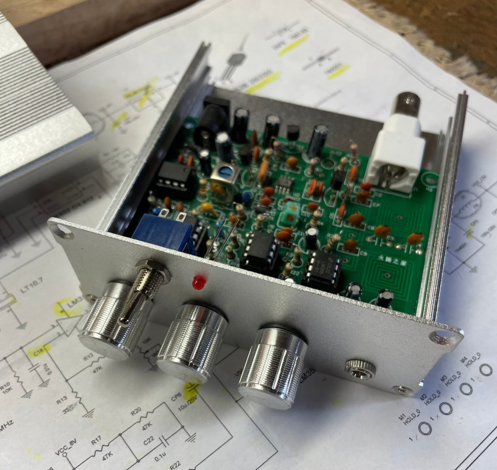
Here is the radio just about completed. The aluminum case does come with the kit. Actually, pretty nice.
I also consulted the web for an antenna design. You can’t pick up radio signals without an antenna…
… but that’s another build and post!