A Dahlia is a tuberous plant that produces incredible flowers. They are in the same family as the sunflower, daisy, and chrysanthemum.

Dahlias do like full sun, however, not “hellish-like” sun that we sometimes experience. Last summer we decided to put up a temporary lattice cover over the plants. That really made a difference in the flower’s longevity. In other words, it kept them from ‘spontaneous combustion.’
The lattice worked so well, I thought I’d design a more permanent set up. I came up with this idea using two 4′ x 6″ high poles, with a lattice-hinged top. The hinges allow you to rotate the lattice upward, and out of your way, for work on the dahlias.
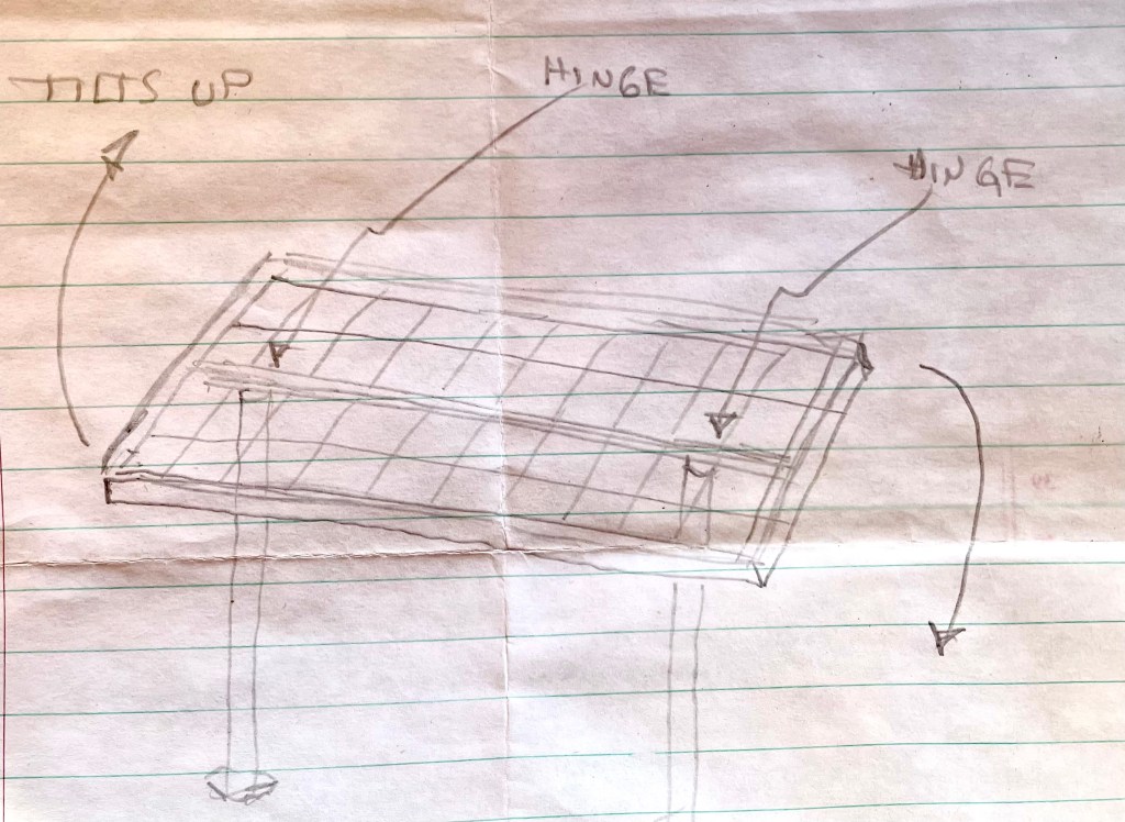
I began by cutting the lattice to size and framing it. See my post Privacy Fence Toppers for tips on framing lattice. I learned a lot on that project.
I attached a piece of 2″ x 3″ lumber (the length of the lattice) on the backside. This will sit on top of the two poles, and the hinges will be attached to it as well.

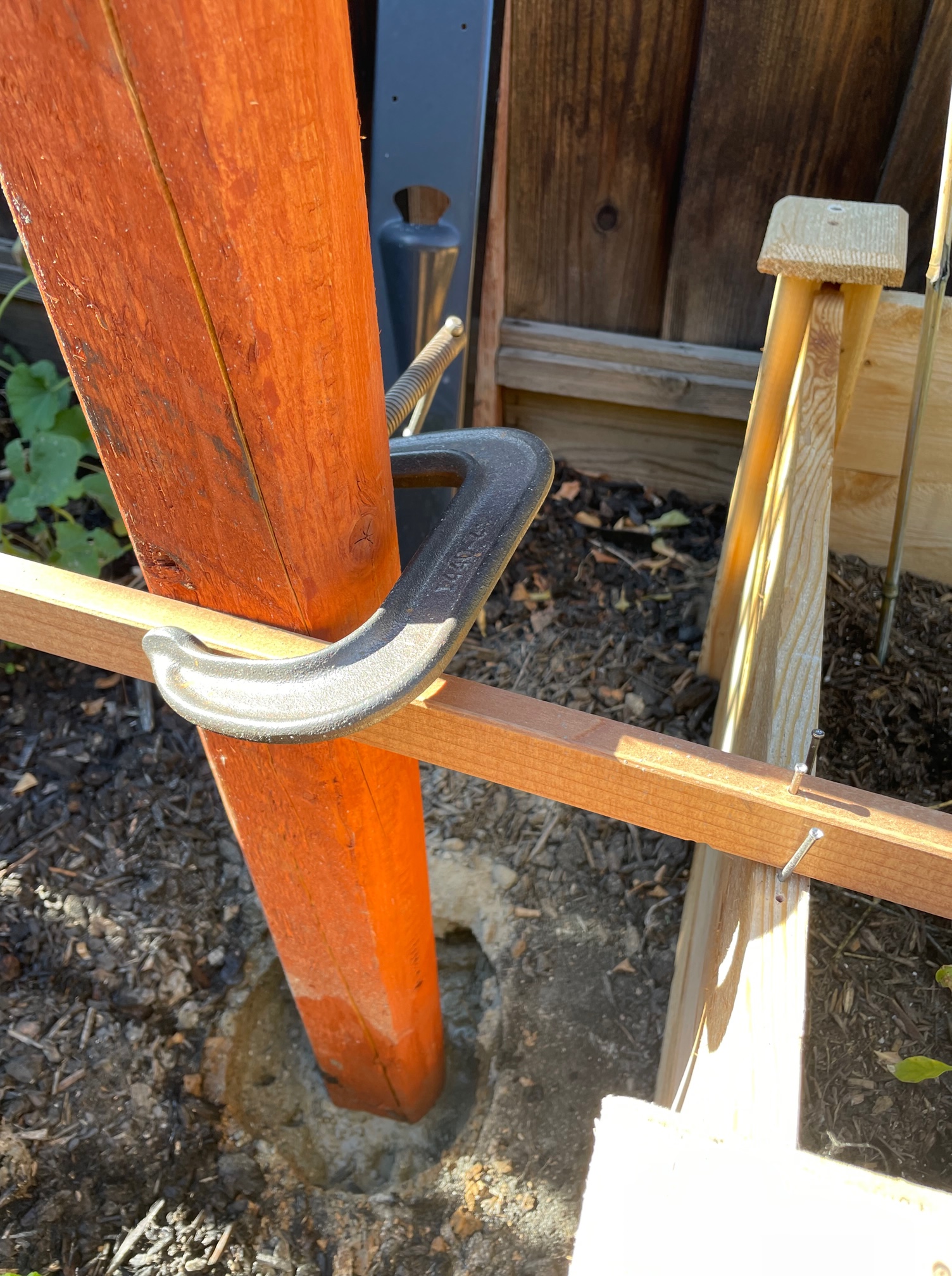
There was already an exiting post on the left side, so I only had to dig one post hole (oh what fun!). The poles will not support much weight, so I dug down 15 inches.
I leveled the post to make sure it was straight, and then secured it. I bought some ‘quick dry’ concrete to set it in position.
Tip: Do not cut your poles to the desired height until set in concrete. Once set, then cut them. Post holes are often dug to different depths. If you precut the poles, and then set them in concrete, you will likely find that your poles are all at different heights. This will make you very unhappy.

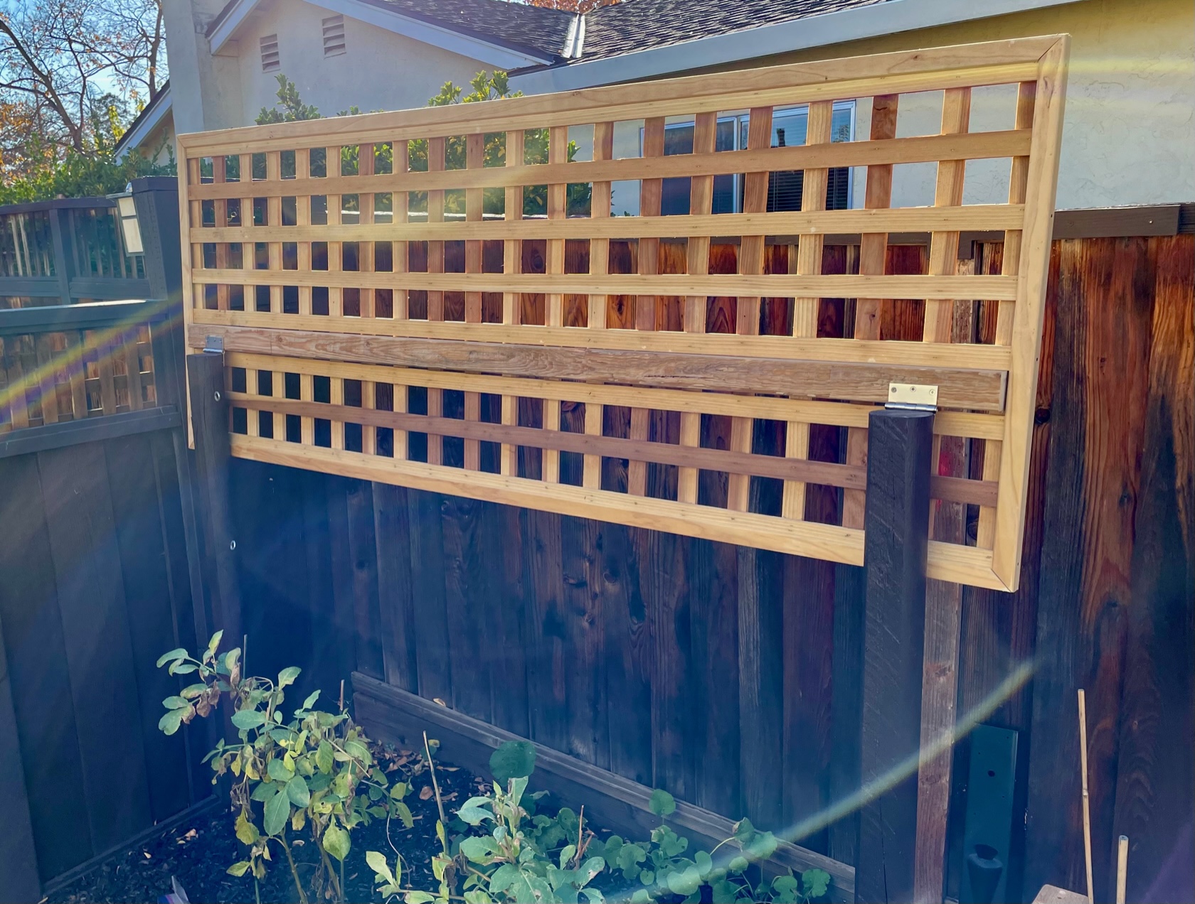
I attached the lattice top to the poles using two hinges, one for each pole.
Here is the hinged top in action – down, providing shade, and up, providing plant access.
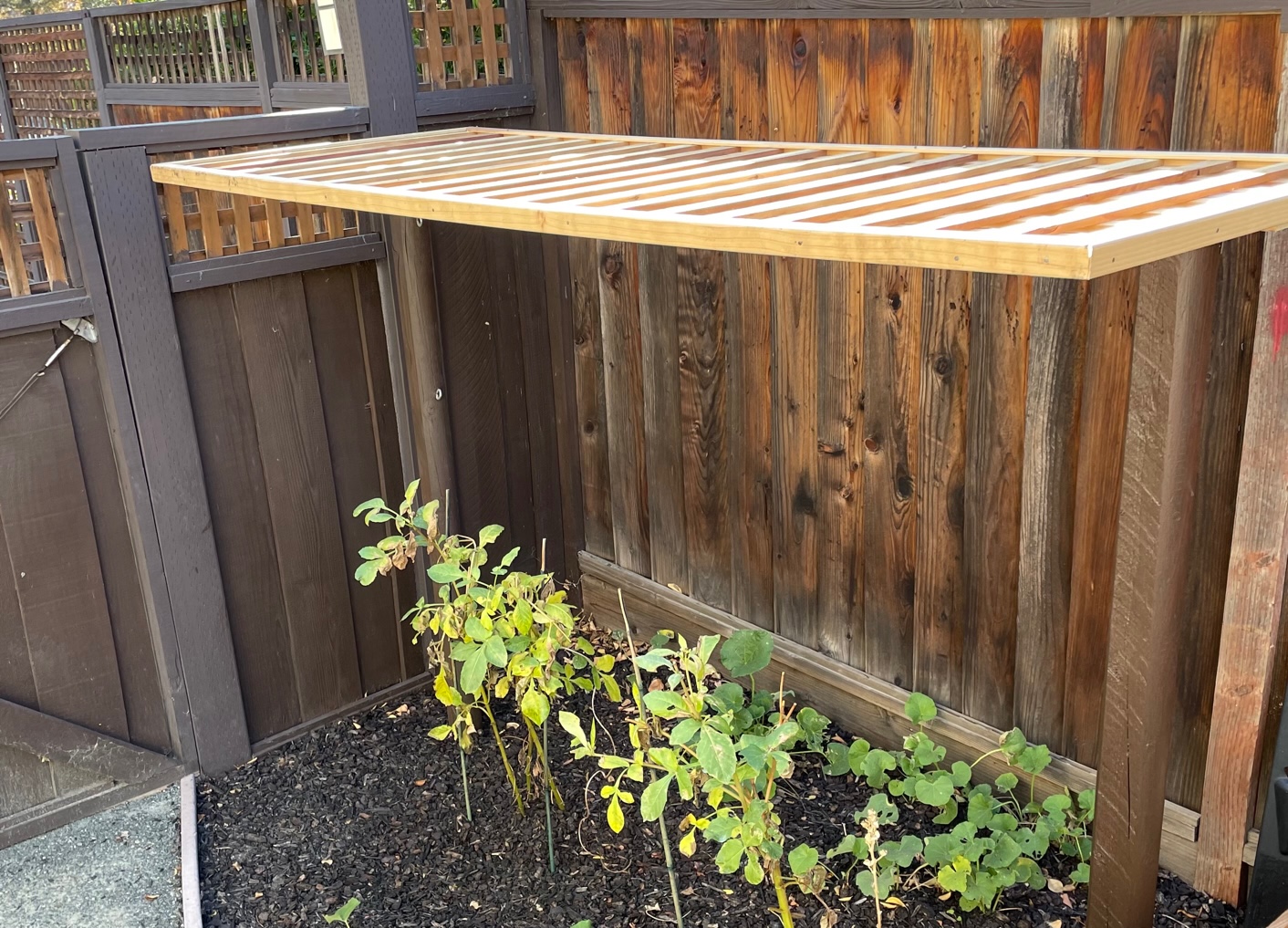
Probably overkill, but I like it.