I’ve been using my viewing device (Pattern Disc Viewer) to help condition me while awake, to hopefully induce marine mammal communication-related dreams at night.
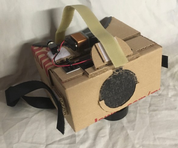
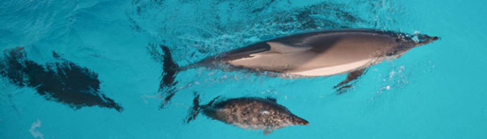
Using the image below, via the viewer, I focus on it for a specified period of time.
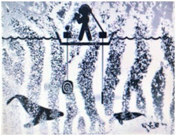
I began to use the viewer for 15 minutes a day, after three days of use I had the following dream.
Pattern Disk Viewer Dream #1:
I was working in the garage, and noticed that one of my molars felt loose. I barely touched the tooth and it fell out. I was not too happy about that.
The house and garage were situated near a small ocean bay. I had the tooth in my hand, and noticed movement in the bay. I felt uneasy as I could see the rounded backs of rather ominous-looking orange and black octopus-like creatures.
It seemed like the creatures wanted to take the tooth away from me. I was not about to let that happen, so I walked around the shoreline to the other side of the bay.
While on the other side of the bay, I accidentally dropped the tooth in the water. Suddenly, I could see a group of dolphins. They were bobbing up and down in the water watching me.
Then one of the dolphins said, “He dropped the tooth, we should help him find it.” I recall being surprised that the dolphin spoke. The dolphins came towards me and began searching for the tooth. One of them found the tooth and gave it to me.
That was the dream in its entirety. It was significant for me as it was the first dream that I induced.
Next step is to become lucid within the dream, so that I can carry on a full conversation. More on this in future posts.